
Increasing the stiffness of the WAW velomobile composite structure with the aid of FEA (Finite Element Analyses) – Master thesis summary
First let me introduce myself. My name is László Balásházy, and I work as a mechanical engineer at Cadterv.hu. I graduated last June at Budapest University of Technology and Economics (located in Hungary). I was specialized in polymer engineering which includes composite technologies and design as well. I studied automotive engineering during BSC.
I wanted to create something which is indeed useful during my MSC thesis work and also preferably something which is related to velomobiles. In my opinion these vehicles are healthy and fun alternative to automobiles and bikes, ideal for sustainable transportation. Stephane was very helpful even before the beginning of the project, as he immediately offered me this topic (among others) and spared his time to fine tune the aims of thesis required for the University in no time.
In case you are interested in my Thesis feel free to contact me (on yahoo.com address starting with velolac;))
WHY – The reason for increasing stiffness
Human powered vehicles, like velomobiles run on precious/limited muscle power, which restricts their maximum achievable speed, however it can be significantly increased by reducing the losses (other than adding some help, like e-assist to the vehicle). One of the best example for that, is the recently set human power land speed record by Aerovelo – Eta, 144km/h (89mph) on flat ground, without wind. Note that, those amazing record setting vehicles (so-called streamliners) are purely speed oriented and not safe, nor practical for everyday use. For those additional purposes velomobiles have been developed.
The overall efficiency of every vehicle depends on two things. One is the amount of resistances it has to overcome, that are (in case of a ground vehicle) the sum of rolling resistance of tires (+bearings) and air drag. Rolling resistance is proportional to the weight, and also with the coefficient of rolling resistance of tires (+bearings again). Even though velomobiles are somewhat heavier than regular bikes (10-30% difference including the – not to be forgotten – rider), their air drag is excellent compared to bikes, and basically also to every other ground vehicle available in serial production, making them capable of achieving high speeds.
The other main factor is the efficiency of its propulsion system, which is usually a system made out of subsystems connected in series regarding the power flow, meaning that every component directly influences the final efficiency, or in other words, the resulting effective traction power. In case of HPVs, this means the efficiency of the power source, the human body (digestive system, muscles), then the driveline (pedal – crank – front chainring – chain guiding idlers – rear sprocket – wheel, and also every part supporting these, in particular the composite body), and finally the ground-wheel contact (slip, basically the speed difference of wheel and vehicle, which phenomenon is always present if there is torque transfer present in a rolling contact). Most of these subsystem components are already given, and cannot be changed, or the modification would result only a miniscule improvement which would not make them sensible to imply, and may also adversely affect other important features of a practical vehicle. However, the driveline efficiency can be improved by decreasing the internal friction losses due to the significant pulsating load (force) the rider creates during pedalling on all the components involved. The “weakspot” of a velomobile in this regard is the long and guided chain path, which creates big flexural and compressing load, therefore visible deformations in the body. These deformations require energy input (work) in the system every load cycle which is partially converted into potential energy (like loading a spring) and into direct loss (heat and wear) via the damping mechanisms. In the simplest form, the work done by a force equals with the force (in the direction of displacement) times displacement, which can be expressed in a more general mathematical as follows:
![]()
If the stiffness of the system is increased, the displacements decrease for the same input load, leading to less overall work done on the body-driveline system and more importantly it also means less loss due to damping.
HOW – The FEA
The load case in a high performance composite velomobile like the WAW is very complex, not only because of the diverse geometries and several force inducing points, but also because of the highly varying composite structure. As a result, to better address the source of deformations, it is beneficial to use modern tools, like CAD models and finite element analyses (FEA).
The flowchart of the development via FEA can be seen on the following picture:
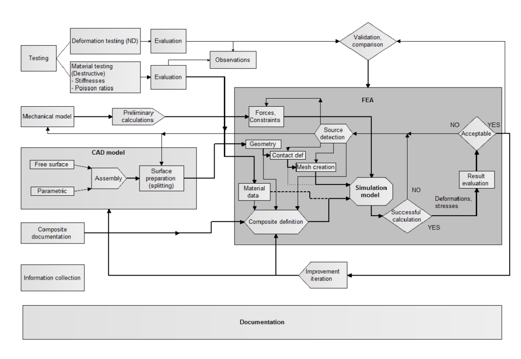
Simulations show the results of a mathematical and physical model based on the given inputs, so care must be taken while defining them, even more so, as often the inaccuracies are not trivial and could lead to misleading conclusions. In case of composites, it means numerous material testing is needed (unlike for isotropic materials like metals, where big databases can provide sufficient data) and the importance of validation is also quite high.
The strength and stiffness of composite materials depend not only on the type of fibers used, fiber content (and voids, etc), but also highly dependent on the orientation of the reinforcing fibers, the layup of the composite laminate. If the load case and geometry permits unidirectional (UD) layers can be used to significantly increase mechanical properties in their used direction.
In the following video a tensile testing can be seen. Some UD specimens gave up at more than 7 ton equivalent of force, no surprise they made a big bang when finally failing. Hard to imagine about 5-6 modern cars worth of weight being held by a small piece of plastic! Ok, not so ordinary plastic, reinforcing fibers really make a difference :).
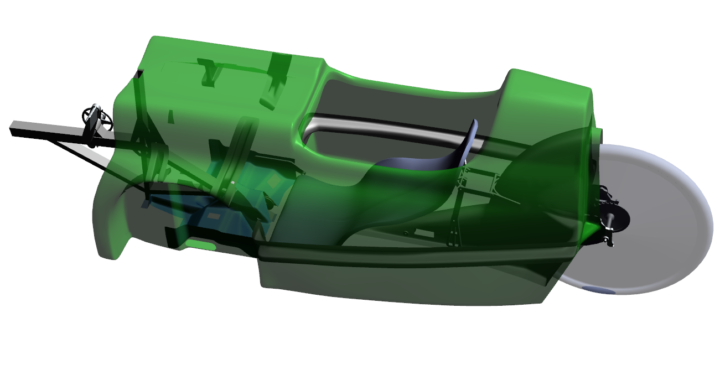
Another important input for the analyses is the CAD model, but before that a simplified mechanical model is beneficial to create, not only to calculate the input loads and constraints for the simulation setup, but also to be able to determine what is necessary to model in the first place, and what can be simplified without sacrificing considerable accuracy. As a result, only the middle (main) section of the WAW has been 3D modelled, including the composite shell, stiffeners, and most metal parts excluding the front suspension.
When the geometry is ready, the next task is to add material data which mainly consist of the time-demanding definition of the composite layup. This is followed by creating contact surfaces where parts meet and the discretization of the geometry (mesh generation), and finally applying the pre-calculated loads and constraints. After setting up the model it can be sent to the solver and then results can be inspected with various methods within the software. If everything seems ok, the results should be compared with real tests to further increase reliability and accuracy.
Here is the real static test (with a blocked rear wheel):
During this test all the available leg force was used in order to better visualize and validate the model. Even though I cannot consider myself as a strong rider I was able to produce 1400+ Newton, resulting in roughly 220Nm of peak torque at the crank. At a high performance cadence rate of 100rpm it would mean about 1300W power which is several times higher than the sustainable power level for even the strongest riders. Deformations can be considered proportional (in this load region) to the forces, so we can esteem that the original WAW is already quite stiff, though there is still some room for improvement.
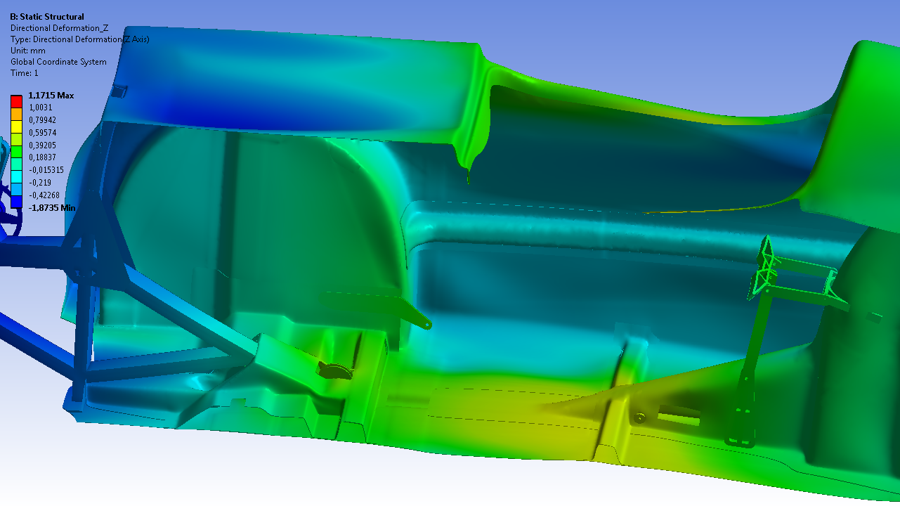
The next one shows simulation results, the equivalent strains (local deformations) from the right side of the original WAW. Note, that for a better visualization the deformations are scaled up 40x in all the animations and pictures, otherwise they would be hardly visible and harder to understand.
The driveline related structure of the WAW is somewhat different from other velomobiles. For example, the “boom” is not connected to the front of the body because of the modularity of the WAW. This is not in favor for stiffness, however it is compensated to some extent by the top attachment of the aluminium frame.
It is also not common among other velomobiles that the monocoque body is reinforced with glued in CF stiffeners, even though it gives the opportunity to increase the flexural stiffness of the body more efficiently, requiring less material and/or use less stiff fibers resulting in the same overall stiffness. This allows the use of aramid (Kevlar also refers to aramid, but it is just a trade name) giving other advantages like shock-absorbing and good passive safety behaviour.
RESULTS, CONSLUSIONS
Even though there were numerous simplifications in the simulation model, the calculated final displacements came really close to the contrast tracking optical measurement results, less than 10% difference at the critical area of front chain idler.
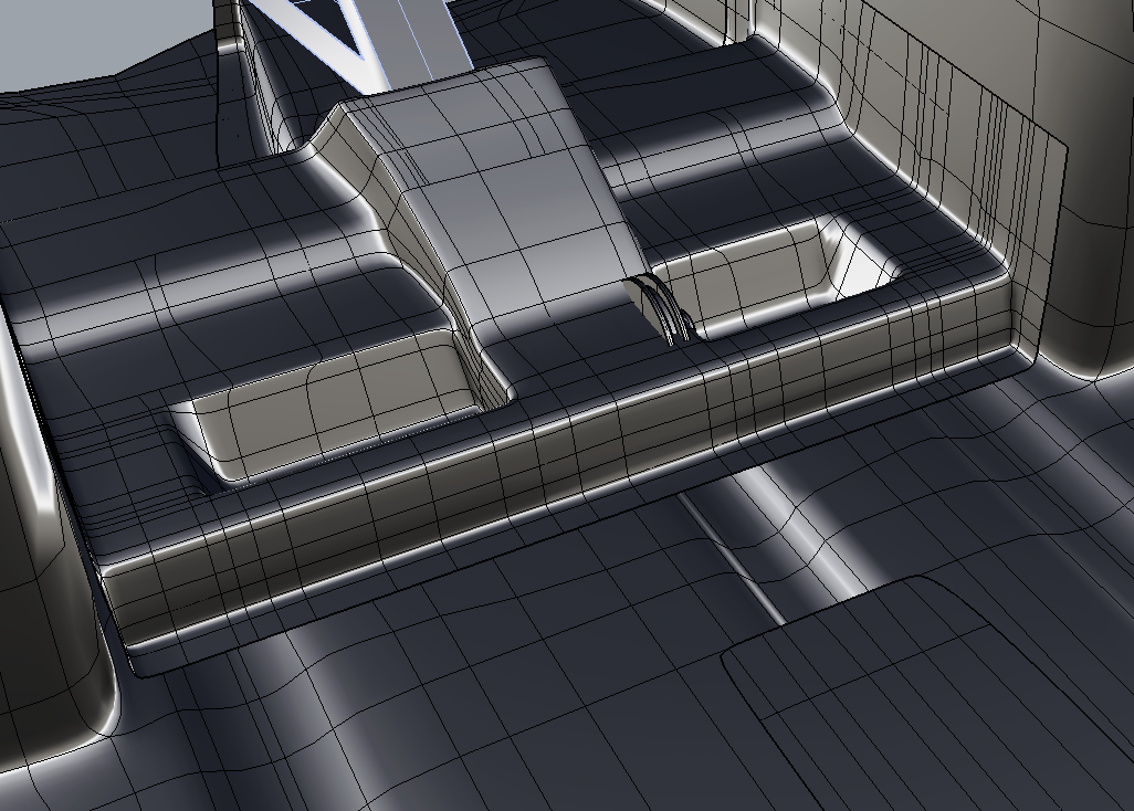
After analyzing the results, several improvement possibilities have been worked out, and the more viable ones simulated and further improved virtually in iterative steps via simulation. The final versions can be seen in the following animation and pictures.
The displacements in the composite body originated mainly from flexural loads as expected, so the modifications aimed mainly the increase of flexural stiffness by achieving high second moment of inertia, which is very highly dependent on the height of the structural member. So the main upgrades:
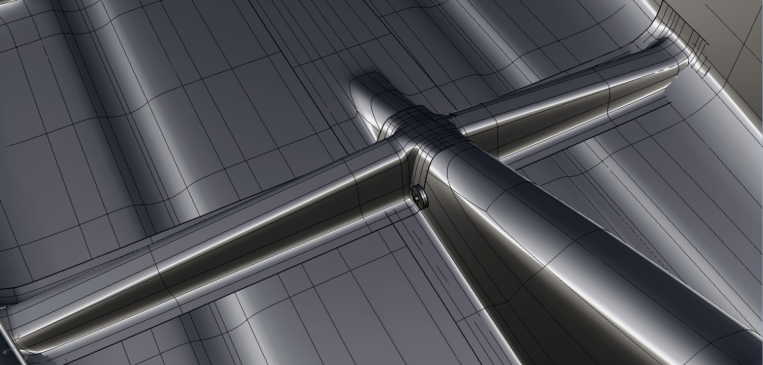
- modified front bridge with improved material use around front idler, integrated lateral omega which also results in a bathtub-like volume which can be used for storing small things too 🙂
- a new lateral omega at the rear chain idler
- slightly modified composite layers around the affected areas
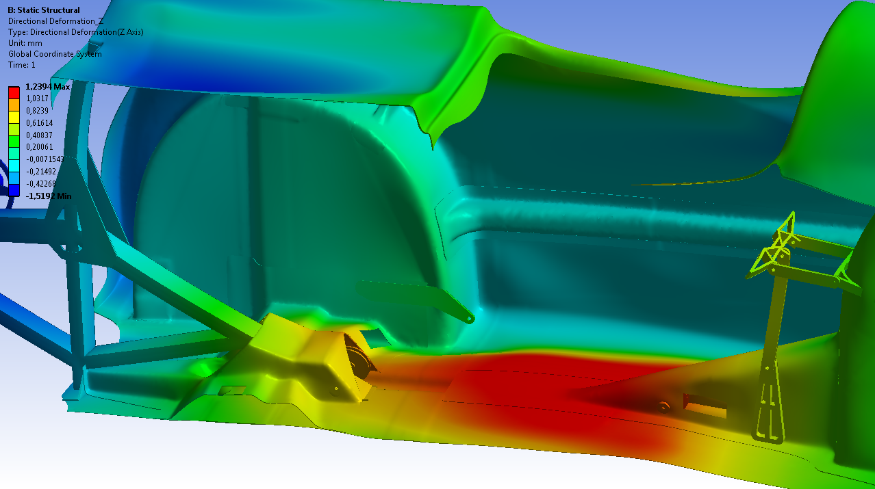
According to the simulation results, the front idler displacement is decreased from 0,84mm to 0,32mm at the simulated high torque level (colour scale is the ~same for both pics, and are also 40x scaled up).
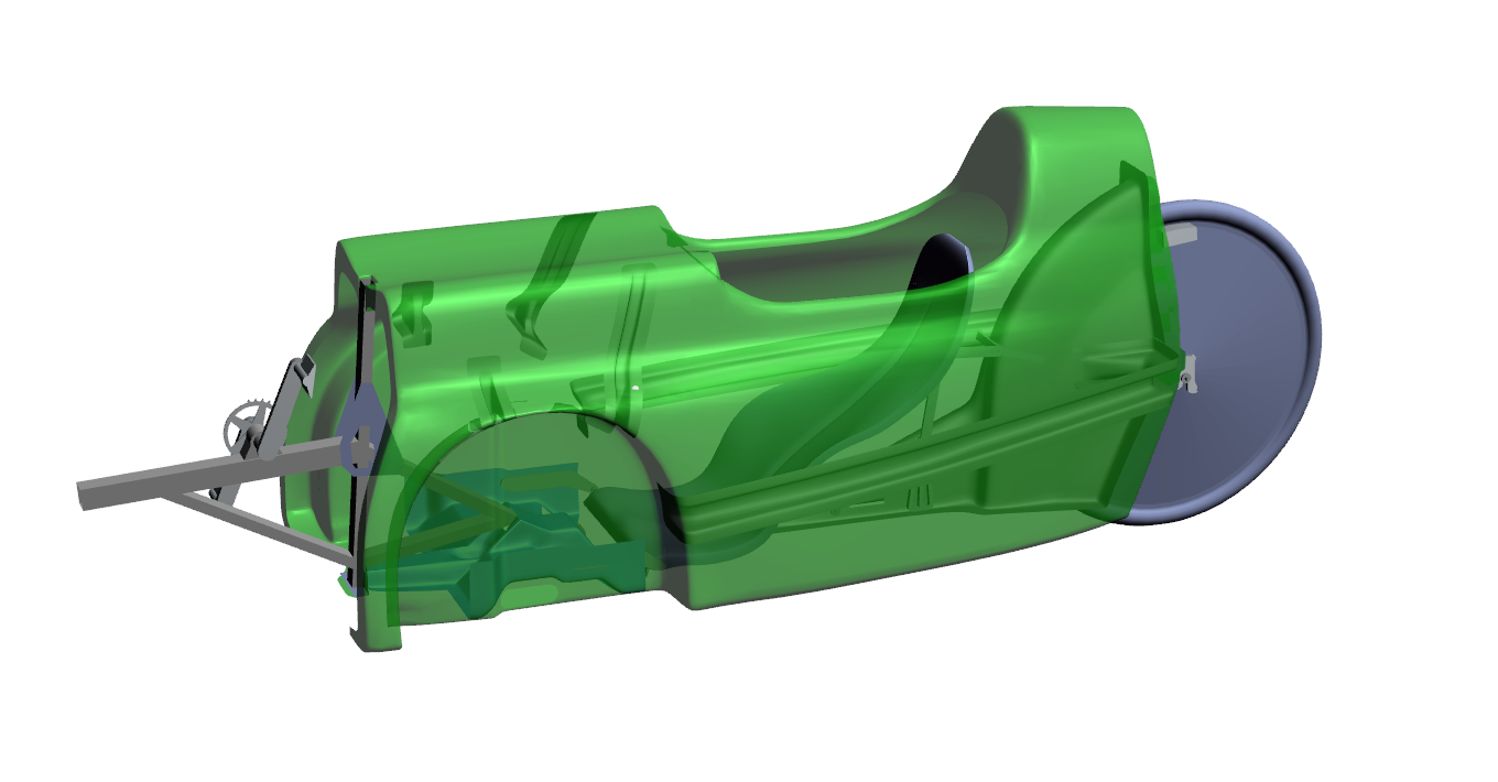
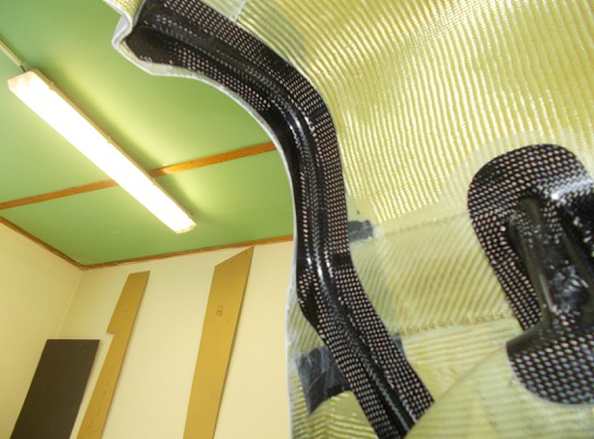
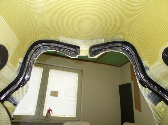
Simulation results led to real products, which can be seen in the following pictures together with the original base free-surface models.
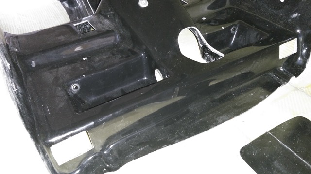
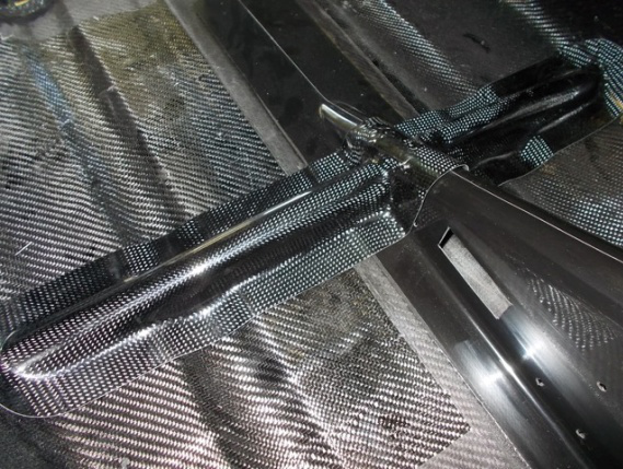
Based on the simulation and measurement results, the body have been further stiffened in the front top section as well, although it was done after my project, so there is no CAD or FEA results available.
From this project the following conclusions could be made:
Finite element method is a good tool, however in normal market conditions it needs high production volumes to make it economically viable. Not only the cost of these software are quite high, but an experienced engineer is also needed to use them to provide reliable results fast. On the other hand they can show the exact behaviour of the system (model) and most importantly the number of iterative tests could be lowered, and there is also no need to realize every prototype version, greatly reducing the overall time for development, achieving the same effect compared to the more empirical velomobile development method.
If my project would be continued it would be easy to carry out numerous analyses with the complete CAD+FEA model I have created. Some examples:
- simulating the driver weight load on the chassis, also when entering/exiting the velomobile creating concentrated forces
- effect of brake and cornering forces
- behaviour of the structure during a crash
- weight minimization with taking into account all the possible load cases and with failure analyses, fatigue calculations.
It should be noted that decreasing the weight has some practical limitations originating from manufacturing (layer type and count => cost and time) and robustness is also beneficial.
Unfortunately no comparative test has been done, however the stiffness of the driveline is definitely improved and Stephane tells it can be felt too. Precise measurements would be nice to make, hopefully there will be time for it. 🙂
6 Comments
-
Stéphane :: February 5, 2017 at 5:09 pm ::
-
Mike Croker :: February 5, 2017 at 6:45 pm ::
-
romain :: February 5, 2017 at 10:21 pm ::
-
Rinus :: March 14, 2017 at 11:15 pm ::
-
Martinius Berg :: January 5, 2018 at 7:18 pm ::
-
Carsten :: September 1, 2021 at 12:20 pm ::